 |
|
TEACHING OLD PINBALL MACHINE NEW TRICKS |
| Report by Daniel Wong & Sven Koenig The University of Southern California (USC) Pinball Project started in the summer of 2008 with the goal to reprogram an existing pinball machine. It started with a Lord of the Rings pinball machine from Stern, a PC and one undergraduate student and has grown within a year to more than five students who are advised by Sven Koenig, an Associate Professor of Computer Science. The USC Pinball Project, supported by the National Science Foundation, is one of the many projects that complement the recently started Bachelor's Program in Computer Science (Games) and Master's Program in Computer Science (Game Development) at USC. Pinball machines have been used before to study and teach real-time and embedded systems as well as signal and image processing. Some previous efforts controlled only the flippers by modifying the hardware, others tracked the ball via input from the playfield switches or an overhead camera, and even others mimicked the microcomputer-based control unit to read the switches and control the solenoids. The goal of the USC Pinball Project,
on the other hand, is to control all aspects of an existing solid-state
pinball machine without having to modify its hardware. It achieves this goal
by developing a hardware and software interface between the pinball machine
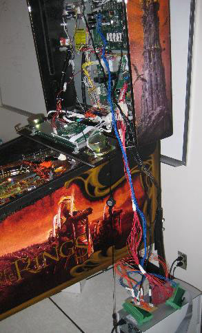
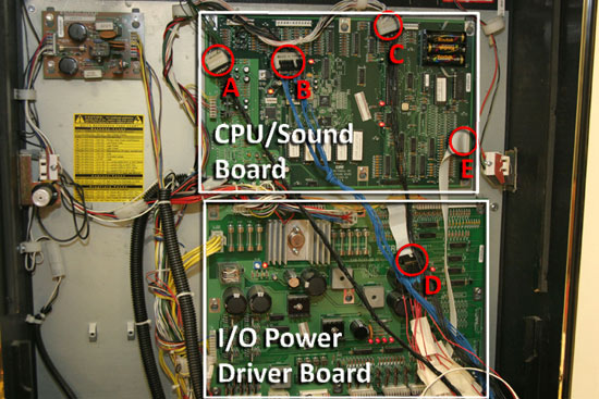
The hardware interface consists of a Switch Detection Board (to filter the switch signals), a Microcontroller Demo Board (to drive the dot matrix display), which interfaces to the PC via a USB connection, and a Digital I/O Card, which interfaces to the PC via a PC card slot. The Lord of the Rings pinball machine contains the CPU/Sound Board, the I/O Power Driver Board and the Dot Matrix Display Controller Board mounted on the rear of the display. The hardware interface plugs into these existing boards using only the five connections shown in Figure 2. Connectors A, B and C connect the Digital I/O Card to the switch signals via the Switch Detection Board and are used to read the status of the switches. Connector D connects the Digital I/O Card to the Power Driver Board and is used to control both the lights and solenoids. Connector E connects the Microcontroller Demo Board to the Dot Matrix Display Controller Board and is used to control the dot matrix display.
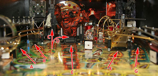
The software interface runs under Linux and is written entirely in C/C++. Sound and video are handled through SDL, a common software multimedia library, while the input and output signals are handled by the Digital I/O Card drivers. The software architecture is constructed in three layers. The lowest layer consists of the hardware interface layer and it communicates with the various boards through the Digital I/O Card. The intermediate layer consists of the behavior layer and it both reads the switches and controls the lights and solenoids. The upper layer consists of the game code and it implements the rules of the pinball game. Darren Earl, a Master's student in computer science, and Fred Zyda, a Ph.D. student in computer science, then used the interface to create a new pinball game. In order to develop ideas for the game, they attended a meeting of the Orange County Pinball League, where they were able to play 15 different pinball machines. They noticed that almost all pinball games follow a pattern where the players need to make a series of predefined shots to move forward in the game. In multi-player mode, pinball games just keep a score for each player with little to no change in game play. Expert players thus often play for long periods of time while the rest of the players sit idle. This insight resulted in three design goals. First, the sequence of shots required to win the new pinball game should be determined during the game. Second, the actions of one player should affect the game play of subsequent players. Finally, the playtime of each player should be limited. The resulting two-player game is called Pinhorse. The first player has one minute to make as many shots as possible. Currently, pinhorse has the seven shots shown in Figure 3 below: left orbit (A), left ramp (B), tower (C), middle orbit (D), center ramp (E), right ramp (F) and right orbit (G). Pinhorse records the shots and uses both sound and light effects to confirm them to the player. It informs the player about the remaining time through both a countdown timer on the dot matrix display and accelerating circular light patterns on the playfield. The second player then has to replicate the shots of the first player in order. Pinhorse informs the player of the next shot through both light effects on the playfield and messages on the dot matrix display. Originally, Pinhorse was meant to incorporate the direction in which the shots are made but this functionality was never implemented.
Pinhorse is a proof of concept game that demonstrates what can be accomplished with the interface. It incorporates almost all of the playfield parts as well as the dot matrix display and sound but needs to be developed further to reach the sophistication of existing pinball games. The development of the interface and game continues. The software interface is currently being restructured and the hardware interface is undergoing a complete makeover to improve its performance. More information on the USC Pinball Project, including a YouTube
video on both the interface and the game, is available at idm-lab.org/pinball.
|