INTRODUCTION
Logic probes have been used for decades to troubleshoot electronic circuits. Logic probes are test instruments used to determine the voltage level of digital logic circuits, both TTL and CMOS.
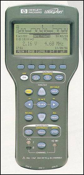
Over the years, logic probes have ranged in: prices, functionality, and features. They may be very simple or very complex.
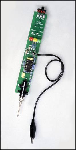 
The picture of the simple logic probe, on the left, is courtesy of Altronics .
The other picture of the complex probe is courtesy of NDSU .
PURPOSE
Though information on the subject if using a logic probe to troubleshoot pinball boards is available on the Internet, that information is usually board/system specific. This introductory seminar will use a general and common circuit, which is used in pinball machines, to teach you general use of a simple and inexpensive logic probe.
The simple probe was chosen for several reasons. Besides being affordable and easy to purchase, the simple probe would also be easier to use. Though the simplicity of use has test limitations, it is the opinion of the author that more complex troubleshooting can best be done with an oscilloscope.
Electronic troubleshooting with the use of an oscilloscope will not be covered in this seminar. Digital Logic or Boolean algebra will also not be covered in this seminar. But, at the end of this seminar you should be able to use a logic probe with proficiency and comfort.
ELECTRICAL SAFETY
Safety first is not just an expression. Safety is the first and most important aspect of dealing with electricity; including electronic troubleshooting. The circuit used in this seminar and boards in your pinball machine(s) must be powered up for you to be able to perform electronic troubleshooting. If you do not feel comfortable testing a circuit that has voltages applied, do not attempt troubleshooting. Improper troubleshooting my damage the circuit under test. I recommend that, if especially you are a novice at electronics, and troubleshooting with a logic probe gives you more questions than answers, that you send your board in for repair. The subject of pinball board repair houses has been covered on the pinball newsgroup; rec.games.pinball RGP.
For safety's sake, you must first ensure that your pinball machine is plugged into a property grounded three-prong AC circuit. This type of circuit can be verified with a circuit tester. If the electrical circuit is not properly grounded, you must call a qualified electrician to correct this potentially lethal problem. If your pinball machine is not properly grounded you must correct this potentially lethal problem before you can troubleshoot any of its boards. If you cannot verify, or if necessary, correct the current going into your pinball machine - stop.
DMM BASIC INSTRUCTIONS
INORMATION
The next step is for you to ensure that the proper voltages are getting to the circuit board(s) to be tested.
The use of DMMs is preferred because they are a hand held piece of test equipment. Many different manufacturers make many different types and styles of DMMs. So, the following instructions will try to be inclusive of many types of DMMs.
For Safety's Sake: Always remember to keep your hands on the plastic, insulated part of your DMM lest leads (or probes) and away from the shinny metal points!
Also, be sure to contact ONLY the one pin or leg of the component under test with the RED test lead tip while keeping your BLACK test lead tip on ground.
HANDS-ON
- Bring out your DMM.
- Insert the plug of the RED test lead into the jack that is labeled: RED, and/or +, and/or V, and/or Ohm, and/or the Greek symbol
 (omega). (omega).
- Next insert the plug of the BLACK test lead into the jack that is labeled BLACK and/or -, and/or Gnd, and/or with the symbol
 (ground). (ground).
- Turn on and/or set your meter to read VDC or - - -. Preferably, leave your DMM in auto mode. If Auto is not available in your meter, set your DMM to measure the largest scale or largest reading. I.E. 1000 Volts Not 10 Volts.
- Now, touch and hold the points or probe ends of your test leads together.
- You should see: 0 or 0.0X (where the letter X is representing any number of 0s) in your meter's display. This represents a reading of no (zero) Volts. But, you will probably see the number zero (0) followed by a decimal point ( . ) and a few other digits. (i.e. 0.02 Volts or 0.10 mV)
- If you did not get an intelligible reading, set your probes in a safe place, with the metal leads not shorting to each other or any other nearby circuit, and adjust your range down to the next smaller scale or reading. Repeat this step until you can verity the reading you were looking for above.
- Now, set and leave your test leads on the table.
- Your meter should read: OL, or OOL. Or your meter's display may simply flash. And/or your display my flash OL, or OOL.
- Set your DMM to the side but leave it set-up in this condition.
TROUBLESHOOTING with a DMM
In a previous seminar we learned that active electronic components work at specific voltage levels. Electronic circuits require certain voltages in order to operate. The first thing to do before automatically going to your logic probe; is to verify that the proper voltages are available on the circuit board(s).
This seminar will utilize a test circuit instead of a board from a pinball machine. Use of the test circuit will teach you how to troubleshoot digital logic without fear of harming yourself or your circuit. The schematic of the test circuit is given near the end of this seminar.
VERIFY Use your DMM to verify that the test circuit is being powered by approximately +9 Vdc and that approximately +5 Vdc is going into the circuit. Finally, verify that the circuit is grounded by the battery's negative terminal. Note: In order to verify proper voltages, you may have to bring down the scale of your DMM. If so, bring down the scale one range at a time and repeat the steps below. Attach the battery to the clip and check your voltages.
+9 Vdc
- First touch the meal tip of the BLACK test lead to the tab of the voltage regulator in the circuit under test.
- While keeping the BLACK test lead in place, touch the meal tip of the RED test lead to the VIN test point of the CUT.
Record your voltage reading __________ Vdc.
+5 Vdc
- Put the meal tip of the BLACK test lead back on the tab of the voltage regulator.
- While keeping the BLACK test lead in place, touch the meal tip of the RED test lead to the VOUT test point of the CUT.
Record your voltage reading __________ Vdc.
GROUND
If you got approximately +9 Vdc for the VIN reading and +5 Vdc for the VOUT reading, you used the proper ground. If you got a 9 and 5 Vdc prospectively, you had the BLACK and RED test lead backwards. Try the above steps again and record the new readings. When done disconnect the battery and put away your DMM.
On a pinball circuit board you would first verify that all of the proper voltages are available to the board under test. The voltages and their test points are listed in most pinball manuals. Refer to your game's specific manual for voltage levels and their tolerances. Ground is usually an available test point and is the braiding inside and all over your pinball machine.
Note: Use of a pad of paper and a pen are recommended to record the voltages you first verified at the voltage test points.
LOGIC PROBE BASIC INSTRUCTIONS
INFORMATION
The use of logic probes is often preferred to the use of oscilloscopes because the probes are small hand held piece of test equipment. Many different manufacturers make many different types and styles of logic probes. So, the following instructions will try to be inclusive of many types of probes.
For Safety's Sake: Always remember to keep your hands on the plastic, insulated part of your probes and away from the shinny metal point!
Also, be sure to contact ONLY the one pin or leg of the component under test with the tip of your logic probe.
Another advantage of using a logic probe is that the circuit under test powers it. I recommend that after you verify your +5 Volt DC test point with your DMM; use that test point to power your logic probe. The RED clip lead gets attached to the +5 Volt DC test point. The BLACK clip lead gets attached to the Ground test point or even any of the bare wire braids in a properly grounded pinball machine. I mention this because I know that you would ensure that your pinball machine was properly grounded and that the power supplies were working properly before you did any other troubleshooting.
A disadvantage of most logic probes is the fact that they are voltage dependent. As the circuits they are testing power most logic probes, it is even more important to verity that proper operating voltages are available to the boards. With many logic probes, a supply voltage of only +3 Volts DC may give false or ambiguous logic readings. And, with many logic probes, a supply voltage of +7 Volts DC (or greater) may keep the positive LED (usually GREEN ) indicator lit. With almost all logic probes, a supply voltage of +35 Volts DC, or greater, will damage the probe. A damaged probe can apply voltages to the circuit under test; that may damage that circuit.
USING A LOGIC PROBE
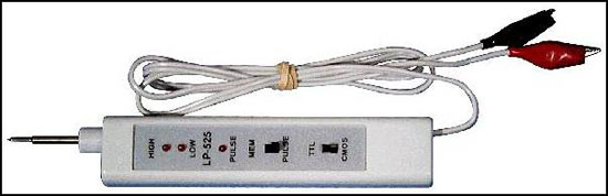
Pictured is the logic probe Mr. Spock prefers.
You can use a logic probe to quickly tell if the pin on the chip you are testing is at either a: HIGH (HI) voltage level, a LOW (LO) voltage level, or changing from HI to LO. This changing is called pulsing. Most logic probes use LEDs to visually indicate the logic level of the pin on the Integrated Circuit (IC or chip) you are testing. In addition to the visual indicators, some logic probes have an audible indicator (buzzer) as well. As the audible indicators are not practical for use inside noisy pinball machines and most certainly inside noisy arcades/bars, only use of the LEDs will be covered. In fact, it is recommended that the buzzer be shut of - on probes with buzzers that have the buzzer on/off option.
The LOW LED (LO) shows Low logic state of a Binary 0. TTL chips consider 0 to + 0.8 Vdc to be low. CMOS chips consider 30% or less of the applied voltage to be LO.
The HIGH LED (HI) shows a logic state of a Binary 1. TTL chips consider +2.4 to +5 Vdc to be high. CMOS chips consider 70% or more of the chip's applied voltage to be HI.
The PULSE LED shows a change of logic level. The change may either be from HI to a LO or from a LO level to HI level.
One limitation of most logic probes is that TTL voltages of +0.9 2.2 Vdc are read as ambiguous or arbitrary voltage levels; therefore none or just the PULSE LED may light. The same is true for CMOS percentages between 31 and 69% of the applied chip voltage.
In general, the 47XX series of chips are TTL and operate from 2 6 Volts.
And, the 40XX series of chips are CMOS and operate from 3 15 Volts.
The explanation of logic states/voltages is shown in summary by the chart below. The next chart is a legend of the different LED's states.
LED States
| Signal |
HI LED |
LO LED |
Pulse LED |
No Connection |
|
|
|
Intermittent Connection |

|
|
|
Logic 0 |

|

|
/ |
Logic 1 |
|
|
/ |
Sq Wave > Operating Freq |

|
|
|
Sq Wave < Operating Freq |
|
|
|
LED Symbols
Symbol |
Meaning |
|
LED Dark (LO or 0) |
|
LED Lit (HI or 1) |
|
LED Blinking Steadily |
|
LED Quickly Flashing |
An explanation of the LED Stages chart follows:
NO Connection (NC)
If your logic probe (LP) is powered by the circuit under test (CUT), but the probe tip is not touching any pins:
The HI LED will be dark.
The LO LED will be dark.
And the PULSE LED will be dark.
Intermittent Connection
If the tip of your probe tip is not making good contact to pin on the CUT:
The HI LED will be flashing quickly/sporadically.
The LO LED will be flashing quickly/sporadically.
And the PULSE LED will be flashing quickly/sporadically.
LO Voltage Level or Logic 0
With good/steady contact to pin on the CUT:
The HI LED will remain dark.
The LO LED will remain lit.
And the PULSE LED may briefly flash at first contact, but then remain dark.
HI Voltage Level or Logic 1
With good/steady contact to pin on the CUT:
The HI LED will remain lit.
The LO LED will remain dark.
And the PULSE LED may briefly flash at first contact, but then remain dark.
Square Wave Read by LP
With good/steady contact to pin on the CUT:
The HI LED will blink at a steady rate.
The LO LED will blink at a steady rate.
And the PULSE LED will quickly flash at a steady rate.
Square Wave Too Fast to be Read by LP
With good/steady contact to pin on the CUT:
The HI LED will remain dark.
The LO LED will remain dark.
And the PULSE LED will quickly flash at a steady rate.
HANDS-ON
Put the IC and transistor into their sockets on the test circuits. The orientation/polarity mark on the IC goes on the notched end of the chip socket. The flat side of the transistor goes to the outer edge of the circuit board. Now, bring out your logic probe and finally reattach the battery to the test circuit. Ignore the LEDs for the time being. Check for LO and HI logic levels.
LO
- First attach the meal clip of the BLACK power lead to the tab of the voltage regulator in the circuit under test.
- Now attach the meal clip of the RED power lead to the VOUT test point.
- Touch the meal tip of the LP to Pin #8 of the CUT.
Record your logic level reading __________ .
HI
- Leave the BLACK and RED power leads in place.
- Touch the meal tip of the LP to Pin #1 of the CUT.
Record your logic level reading __________ .
The PULSE LED may have briefly flashed as you made contact to Pin #8, but the LO LED should have stayed lit. And, you should have recorded a LOW (LO) for the first logic reading.
The PULSE LED may have briefly flashed as you made contact to Pin #1, but the HI LED should have stayed lit. And, you should have recorded a HIGH (HI) for the second logic reading.
If you did not get these results, first verify that you have the probe clips attached to the correct power points. Then verify that you probed Pins #8 then Pin #1 on the CUT buy reading pins #8 and #1 of the CUT again. Re-record the correct results.
TROUBLESHOOTING with a LOGIC PROBE
Look at the schematic of the test circuit. Use the LP and the LEDs in the CUT to troubleshoot the test circuit.
Schematic
This is the “clock” portion of the schematic. The clock in the CUT represents the CPU of a pinball machine. You have already checked pins #1 and #8. Some logic probes cannot read the clock pins, but they can read the state of the other pins.

This is the control and output portion of the CUT. This portion of the schematic is like the driver board of a pinball machine. Notice that Pin #5 of the clock portion is connected to Pins #5 and #7 of the control/drive portion via the “out” and “in” arrows. Also notice the three other sets of pins that are connected. Record the three connected sets of pins.
Pin #____ to Pin #____,
Pin #____ to Pin #____, and Pin #____ to Pin #____.
You should have noticed that their same common line connects Pins #6 and #9.
You should have noticed that Pins #10 and #11 are connected by their same line.
You should have also noticed that Pins #12 and #14 are connected by their same line.
If you did not notice the connected pin sets, reexamine the control portion of the schematic and record the correct answers.
Circuit Description
The 4049 in the CUT is a CMOS Inverter IC. The 4049 was chosen because you will be able to use either the TTL or CMOS level selection on your LP. The clock portion toggles HI to LO pulses out from Pin #5 in to Pin #7. Pin #10 drives/lights the LO LED. The LO LED is the indicator that the clock is in its LO half of its cycle.
LO
- Touch the tip of your LP to either Pin #6 or Pin #9 of the IC.
Record the logic level reading on your LP when LED #2 is lit __________ .
HI
- Touch the tip of your LP back on either Pin #6 or Pin #9 of the IC.
Record the logic level reading on your LP when LED #3 is lit __________ .
You should have recorded a “LOW (LO or 0)” for the first answer and a “HIGH (HI or 1)” for the second answer. If not, go back and check your work and fix your answers. Which LED on the CUT and LED on your LP glow when LED #4 lights?
Record the answer about when LED #4 is lit:
____________________________________________________________.
You should have answered something to the effect that LED #4 does not light. From the circuit description, you know that the 4049 is an inverter. From your previous testing, you know that the clock is HI when LED #3 is lit. And finally, you know that the chip is an inverter. So, the LO clock should give a HI output. Think of it the CUT thusly.
So, a HI on pin #15 should turn on the NPN transistor, which in turn, should turn on LED #4.
Pin #15
- Verify that Pin #15 goes high by using your LP.
Record the logic level reading on your LP __________ .
If the clock portion of the CUT eventually drives Pin #15 and its associated electronics HI, why doesn't the LED light? Well, you know it isn't the IC.
2N4401 Emitter (E)
- Verify that the Collector of the transistor goes to VOUT by using your DMM.
Record the voltage level reading on your DMM __________ .
2N4401 Collector (C)
- Verify that the Emitter of the transistor is connected to GND using your DMM.
Record the voltage level reading on your DMM __________ .
You should have recorded about +5 Vdc for the first answer and about +1 Vdc for the second answer. If not, go back and re-verify the proper voltages. Make the corrections.
If the reason that LED #4 does not light is not because of the voltage applied or the operation of the IC, the process of elimination only leaves the following three components: diode, resistor, or transistor. As there is not much to the output portion of the circuit, the chance of an open connection is slim. If you were repairing an actual pinball machine, it would be best to first verify all connections/traces on the circuit board, then you could shotgun all three suspect components. As the transistor is socketed, ask the instructor for a replacement.
New 2N4401
- First, disconnect the battery.
- Then, verify that you have been given the correct transistor.
- Next, install the new transistor in the same orientation as the old component.
- Now, reattach the battery.
- Finally, observe the color of LED #4.
Record the color of LED #4 __________ .
You should have observe and recorded that the color of LED #4 is blue.
This ends the text and lab portions of the Logic Probe Seminar. Next is the written test. Proceed to the end of seminar and take the written test.
GLOSSARY
| AC |
An acronym for, Alternating Current. |
| Boolean Algebra |
A branch of algebra in which elements have a value of zero (0) or one (1). And, the algebraic operations use of AND / OR are added and multiplied. |
| CMOS |
An acronym for, Complementary Metal Oxide Semiconductor. |
| Current |
Measured in Amperes, current is the flow of electricity in an electronic circuit. (Think of electrical current as the flow of water in a river. The wider the river, the greater the amount of flow.) Safety rule - amps kill! |
| CUT |
An acronym for, Circuit Under Test. Whereas DUT is an acronym for, Device Under Test. |
| DC |
An acronym for, Direct Current. |
| Digital Logic |
A yes/no system where the voltage level below a certain expected point is considered "no" and given a value of zero (0). And, where the voltage above a certain expected point is considered "yes" and given a value of one (1). |
| DMM |
An acronym for, Digital Multi-Meter. This is a piece of hand held test equipment that allows the testing and troubleshooting of electronic components and circuit boards. |
| Oscillation |
A cycle from it high point through its low point. |
| Oscilloscope |
An electronic test instrument that uses a monotone monitor like display to show trace representing oscillations of voltage and current. |
| TP |
An acronym for, Test Point. |
| Troubleshoot |
To determine the cause of a problem. |
| TTL |
An acronym for, Transistor Transistor Logic. |
| Voltage |
Measured in volts, voltage is the electrical pressure inside an electronic circuit. (Think of voltage as the swiftness of the water in a river. The faster the current, the greater the amount of force.) Safety rule - volts hurt! |
PLACES TO BUY
You can either get a kit (LP-525K LOGIC PROBE KIT) or probe (LP-550 LOGIC PROBE) from the above on line seller. If you are somewhat handy with electronics and soldering, I recommend the kit. If you don't feel comfortable, I recommend the probe.
OTHER TECHNICAL REFERENCE
The following on-line reference covers general use of logic probes as well as specific information relating to the use of logic probes to troubleshoot individual pinball boards.
Pinball HQ.com
Author: Clay Harrell
Host: Marvin3M.com
Email: [email protected]
SEMINAR TEST INFORMATION
This following twelve-question test is PASS or FAIL. You must get ten or more correct answers (83%) to PASS. Read each question carefully. Some questions require a written answer, while others are fill-in the blank, some are true/false, and others have multiple choices. This is an open book test.
HANDS-ON
Complete the following twelve questions.
LOGIC PROBE SEMINAR TEST Date: _______________________
Student's First Initial and Last Name: _________________________________
Q1) From the list below select the two most important things to remember when working with any electrical circuit.
A) Safety
B) Stop if you are unsure
C) Clean up your mess
D) Eat right
Q2) From the following list, select what should be verified before your begin any work or any troubleshooting on any pinball machine.
A) Proper grounding
B) Proper voltages going to the boards
C) Ensure that everyone is a safe distance away
D) Proper etiquette
Q3) Select what should be verified before your begin any troubleshooting on any pinball machine.
A) Proper grounding
B) Proper voltages going to the boards
C) Ensure that everyone is a safe distance away
D) Proper etiquette
Q4) Choose what must be verified before your can begin correctly troubleshooting any circuit board on any pinball machine.
A) Proper grounding
B) Proper voltages going to the boards
C) Ensure that everyone is a safe distance away
D) Proper etiquette
Q5) Which is the best voltage to run your logic probe off of / attach your logic probe to?
A) 0.0 Volt DC
B) +3.0 Volt DC
C) +5.0 Volt DC
D) +35.0 Volts DC
Q6) Choose the maximum voltage level for a logical zero (0) on a TTL chip.
A) +0.0 Volt DC
B) +0.8 Volt AC
C) +0.8 Volt DC
D) +5.0 Volts DC
Q7) Choose the minimum voltage level for a logical one (1) on a TTL chip.
A) +0.0 Volt DC
B) +0.8 Volt DC
C) +2.4 Volt DC
D) +5.0 Volts DC
Q8) Circle the correct True or False answer.
A logic level of zero (0) is represented by the binary number 0. True or False
Q9) Circle the correct True or False answer.
A logic level of one (1) is represented by the binary number 1. True or False
Q10) Circle the correct True or False answer.
A bit is an binary toggle, a shift from low to hi, represented by a 0 changing to a 1. True or False
Q11) Fill in the blanks.
A) __________ hurt. B) __________ kill.
Q12) What single thing is the first and most important aspect of dealing with electricity?
_____________________________________________________________
LOGIC PROBE SEMINAR ANSWERS
A1) Only the two following are acceptable.
A) Safety
B) Stop if you are unsure
A2) Only the following single answer is acceptable.
A) Proper grounding
A3) Either or both of the following two answers is/are acceptable
A) Proper grounding
B) Proper voltages going to the boards
A4) Only the following answer is acceptable.
A) Proper voltages going to the boards
A5) Only the following is correct.
C) +5.0 Volt DC
A6) Only the following is correct.
C) +0.8 Volt DC
A7) Only the following is correct.
C) +2.4 Volt DC
A8) Only the following is correct.
True
A9) Only the following is correct.
True
A10) Only the following is correct.
True
A11)
A) Volts hurt. B) Amps kill.
A12) Only the following is acceptable.
Safety
This ends the Logic Probe Seminar at the April 1st Pinball Circus.
Enjoy the Circus! |


